SMT – Surface Mount Technology
Surface Mount Technology – Electronics Parts Assembly Line
Surface Mount Technology is a method in which the electrical components are mounted directly onto the surface of a printed circuit board (PCB). An electrical component mounted in this manner is referred to as a surface mount device (SMD). In industry, this approach has largely replaced the through-hole technology construction method of fitting components, in large part because SMT allows for increased manufacturing automation which reduces cost and improves quality. It also allows for more components to fit on a given area of substrate. The Surface Mount Technology line is part of the Electronic Manufacturing Services at Esko Casting and Electronics Pvt Ltd.
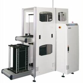
PCB Handling
- Automatic magazine change-over and Inspection Conveyor
- Magazine alignment by upper and lower pneumatic clamping.
- Regulated pressure on pneumatic pusher.
- Tower light display for machine status.
- Selectable pitch settings.
- Conveyor width adjustment using hand crank.
- Inspection and by-pass mode selectable.
- Centre PCB stop position
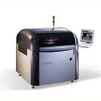
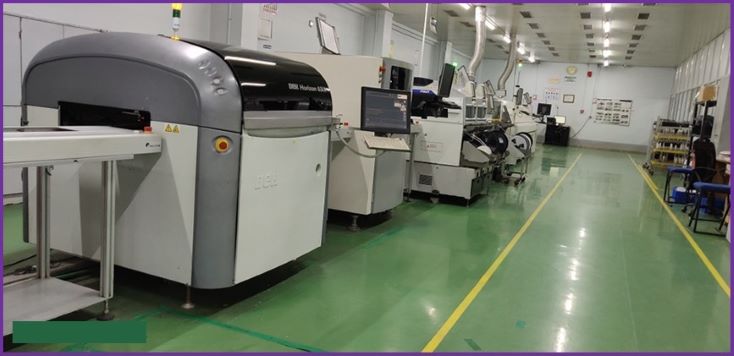
Paste printing Horizon 03iX
- 750 Hawkeye Camera.
- Stencil frame size 29X29 inch.
- PCB Panel size 510 mm x 508.5mm.
- Wet /dry/ vacuum 3 mode cleaning.
- Printing Cycle Time (CCT): 8 sec.
- Motorized with squeegee pressure feedback
- Motorized (actuators); aligned on X- and Y-axis and rotation.
- Machine Alignment Capability: ±12.5 µm.
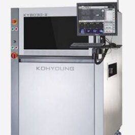
Solder paste inspection (SPI)
- PCB Panel Size: 330 x330mm.
- Automatic Conveyor width adjustment.
- Camera Resolution -15μm , 20μm, 25μm.
- X,Y Positioning Accuracy -2.5nano meter.
- Closed loop Feedback system.
- 3D Inspection Speed-22.5-56.1cm²/sec.
- 100% Paste inspection Height, Volume & Area.
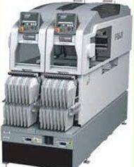
Fuji pick & place (NXT III)
- Panel size -48 x 48 to 534 x 610 mm.
- PCB loading time -3.4 sec.
- Feeder slot quantity- 68×2=136 (8mm)
- Heads-H24S, H24A, DX *1, V12, H12HS(Q),
- H24 -Part size – 0201 to 5 x 5 mm .
- H24 – 75000 cph
- V12/H12HS : 0402 to 7.5 x 7.5 mm
- Placing accuracy-±0.025 mm Cpk ≥ 1.00.
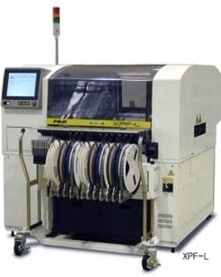
Fuji pick & place (XPF-L)
- Panel size – 686 x 508 mm.
- PCB loading time -1.8 sec.
- Feeder slot quantity- 45×2=90 (8mm)
- Part Size Handling -01005 to 68x68mm.
- Revolver Head: 25,000 cph.
- Single Nozzle: 9,000 cph.
- Glue Tool: 0.2 sec/shot.
- Tray Unit . Handling for tray components.
- Placing accuracy-±0.025 mm Cpk ≥ 1.00.
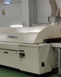
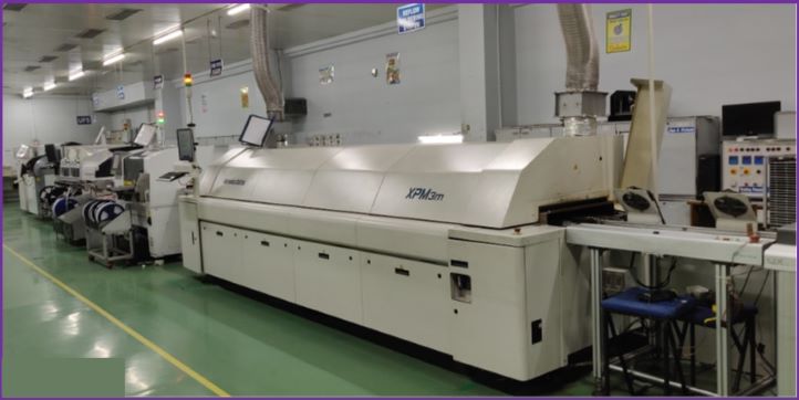
Reflow Oven (XPM)
- Edge and Mesh Conveyor.
- Left to Right Board Flow.
- 102 Inch Heated Tunnel Length.
- 8 heating zones and 2 Cooling Zones.
- Individual zone exhaust of flux contaminants.
- Over temperature switches.
- Safety interlocks on electrical panels..
- Power hood lifts.
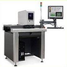
Automatic Optical Inspection (AOI)
- PCB Size-50 x 50 mm to 400 x 308 mm.
- Camera – 40 Megapixel Sensor.
- Resolution – 17 μm pixel size.
- Inspection Speed -200 cm2 /sec (31 in2 /sec).
- Defect Analysis -Missing Parts, Polarity, Tombstone, Billboard, Flipped, Wrong Part, Solder Bridging, Lifted Leads, Excessive Solder, Debris.
- Lighting -Strobe White Light (with dark/bright field).
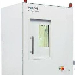
X Ray Inspection
- Sample size 440 x 550 mm
- Inspection area (max.) 310 x 310 mm.
- Oblique viewing -+/-70° (140°).
- Tube type -open X-ray tube.
- Voltage range -25 – 160 kV.
- Current range -0.01 – 1.0 mA.
- Max. tube power -10 W to 64 W.
- Geometric magnification (max.) -2,000 x.
- Total magnification (max.) -17,500 x.
